A heat exchanger works by transferring heat between two fluids at different temperatures without allowing them to mix (in most designs). Heat moves from the hotter fluid to the colder fluid through a conductive surface (such as a tube wall or plate), while fluid motion improves transfer by convection. This is the core heat exchanger working principle used in industrial processes, HVAC, food processing, energy systems, and chemical plants.
If you are comparing industrial solutions, explore XLG’s heat exchanger range.
Quick Answer: How Does a Heat Exchanger Work?
A heat exchanger transfers thermal energy from a hot fluid to a cold fluid by:
- Keeping the fluids in separate flow channels
- Separating them with a thermally conductive wall
- Using temperature difference as the driving force for heat transfer
- Maintaining flow conditions that support efficient heat exchange
The hot fluid cools down, the cold fluid heats up, and the two media remain separated in standard indirect-contact designs.
Heat Exchanger Working Principle (Step by Step)
1) Temperature Difference Creates the Driving Force
Heat always flows from higher temperature to lower temperature. In a heat exchanger, this temperature gradient is what drives thermal energy transfer.
2) Heat Passes Through a Metal Surface (Conduction)
The fluids are separated by a wall (typically tubes or plates). Heat travels through this wall by conduction.
3) Moving Fluids Transfer Heat to/from the Surface (Convection)
Each fluid transfers heat to the wall (or receives heat from it) by convection. Flow velocity, turbulence, and channel design strongly affect thermal performance.
4) Continuous Exchange Along the Flow Path
As both fluids continue moving, heat transfer happens continuously across the available surface area until the fluids exit at new temperatures.
This is why surface area, flow arrangement, fluid velocity, fouling resistance, and pressure drop all matter in real industrial design.
The 3 Heat Transfer Mechanisms Involved
Although heat exchangers are usually explained with conduction and convection, a complete engineering view includes:
- Conduction → heat transfer through the tube/plate wall
- Convection → heat transfer between fluid and wall
- Radiation → usually minor in many liquid-liquid exchangers, but can matter in some high-temperature applications
For most industrial heat exchanger sizing discussions, conduction + convection dominate.
Main Types of Heat Exchangers (and How They Work)
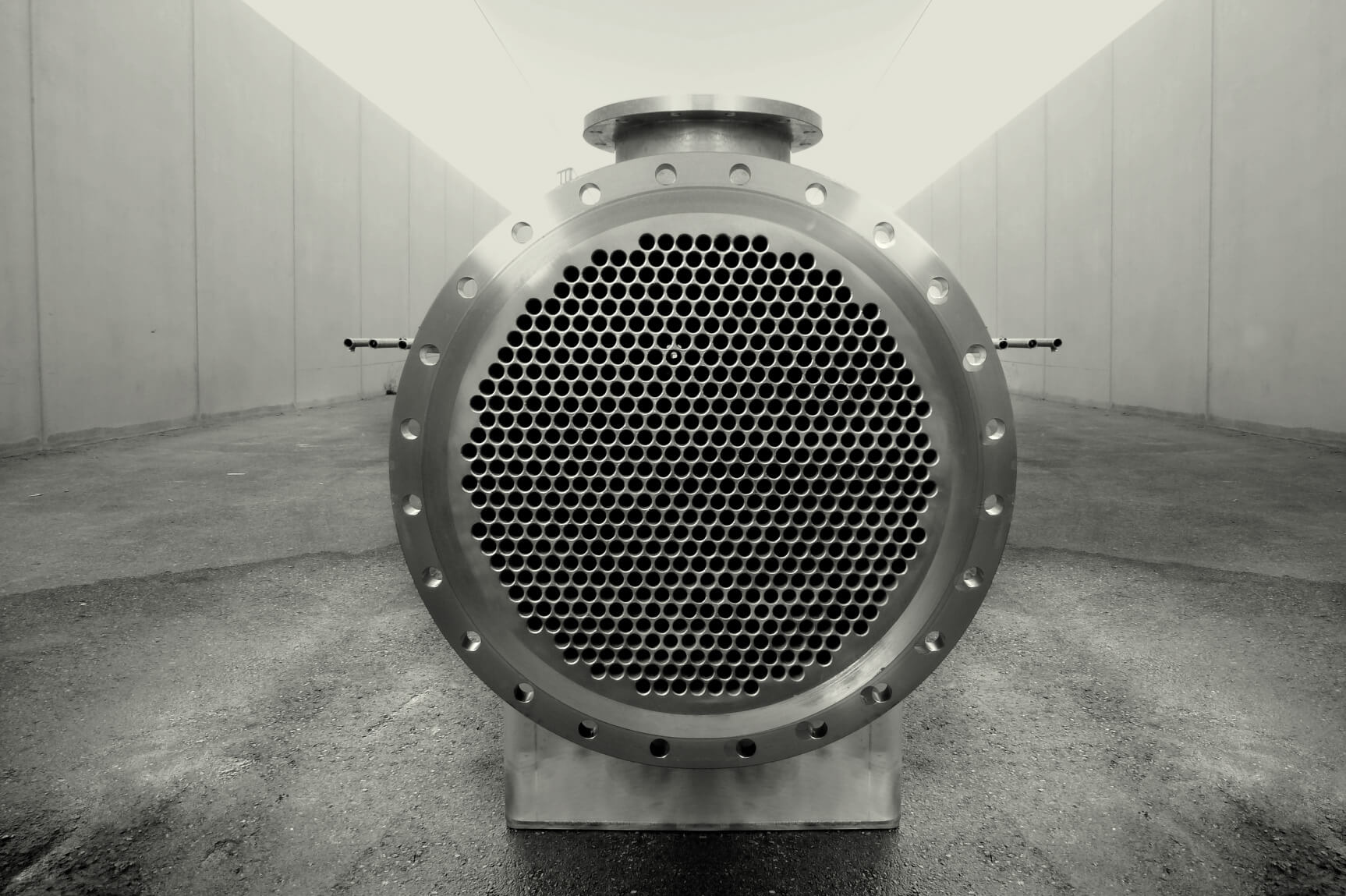
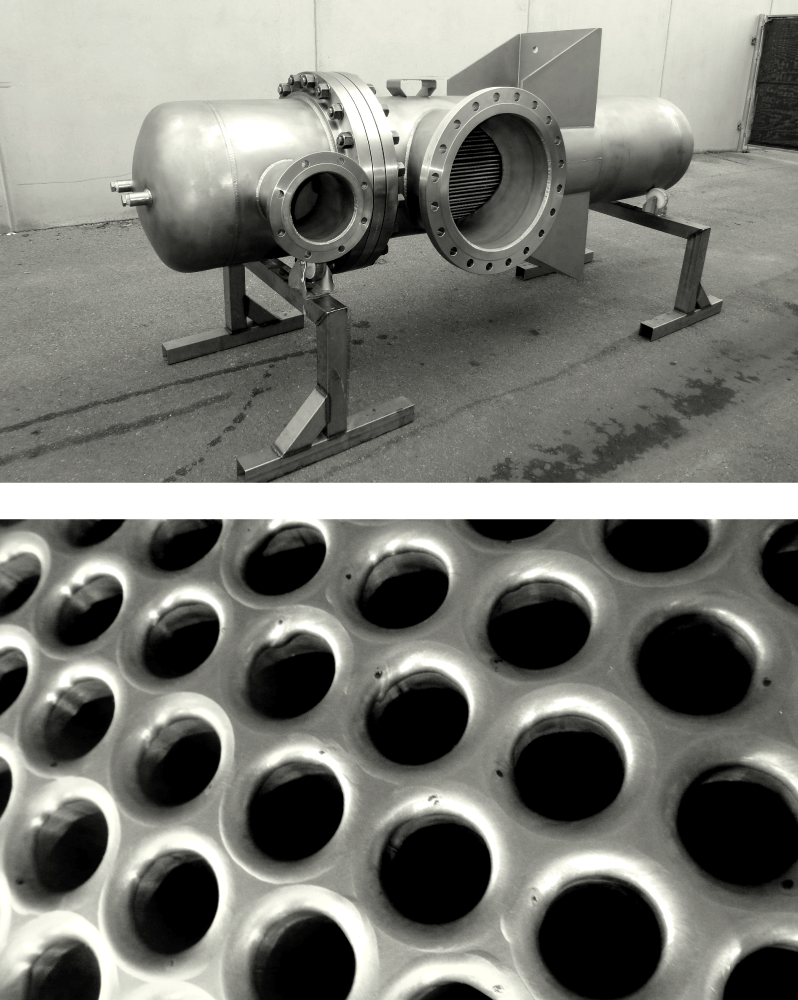
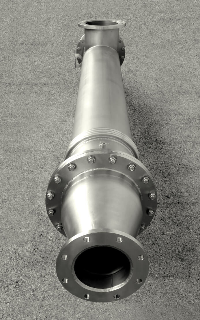
1) Shell and Tube Heat Exchanger
A shell-and-tube heat exchanger uses a bundle of tubes inside a shell. One fluid flows inside the tubes; the other flows around the tubes inside the shell.
How it works
- Heat transfers through tube walls
- Baffles may direct shell-side flow and improve heat transfer
- Multiple passes can increase heat exchange time, but may increase pressure drop
Best for
- High pressure / demanding industrial duty
- Chemical processing
- Energy and process industries
- Fluids with more challenging conditions (depending on design)
2) Plate Heat Exchanger
Plate heat exchangers use multiple thin plates to create alternating channels for hot and cold fluids.
How it works
- Fluids flow in alternating channels
- Corrugations increase turbulence and surface area
- Compact footprint with high heat transfer efficiency
Best for
- Compact installations
- Hygienic processes (with suitable sanitary design)
- Applications requiring efficient heat recovery
Plate designs are often highly efficient, but suitability depends on viscosity, solids, fouling behavior, and pressure requirements.
3) Scraped Surface Heat Exchanger
A scraped surface heat exchanger is designed for viscous or fouling-prone products. Internal scraping action continuously removes product buildup from the heat transfer surface.
How it works
- Product flows through a heat transfer cylinder
- Rotating blades scrape the surface
- Scraping reduces fouling and maintains heat transfer performance over time
Best for
- High-viscosity products
- Fouling-sensitive processes
- Temperature-sensitive product handling
Flow Arrangements: Why Counterflow Is Usually More Efficient
Heat exchanger efficiency depends heavily on fluid flow arrangement:
Counterflow (Counter-Current)
The two fluids move in opposite directions. This typically maintains a higher average temperature difference across the exchanger and improves heat transfer performance.
Parallel Flow (Co-Current)
Both fluids move in the same direction. This is simpler conceptually but often less thermally efficient than counterflow.
Crossflow
Fluids move perpendicular to each other. Common in air-cooled and HVAC-style applications.
Key Performance Factors That Determine How Well a Heat Exchanger Works
1) Heat Transfer Surface Area
More effective surface area generally improves heat transfer capacity.
2) Temperature Difference
A larger driving temperature difference generally increases heat transfer rate.
3) Flow Rate and Velocity
Higher velocity can improve convection and reduce fouling in some cases, but may increase pressure drop.
4) Pressure Drop
A heat exchanger should deliver thermal duty without excessive pressure loss. This is a critical design trade-off in industrial systems. XLG specifically references tube selection according to performance and pressure loss, which is exactly the kind of engineering criterion buyers look for.
5) Fouling
Deposits on the heat transfer surface reduce efficiency over time and can increase operating cost. Fouling control is a major selection and maintenance factor.
6) Material and Tube Geometry
Material selection affects corrosion resistance, cleanability, and thermal performance. Tube geometry can also influence heat transfer and fouling behavior. XLG highlights multiple tube types (corrugated, flat, dimple, oval, twisted, smooth) to adapt performance to operating conditions.
Engineering Terms Buyers Often Search For (and Why They Matter)
Including these concepts improves both SEO topical depth and AI/GEO retrievability:
- Thermal duty: the amount of heat to be transferred
- Overall heat transfer coefficient (U-value): an aggregate measure of heat transfer performance
- LMTD (Log Mean Temperature Difference): a standard method used in heat exchanger thermal calculations
- Approach temperature: the temperature difference at the closest point between fluids
- Fouling factor: design allowance for expected surface buildup
- Residence time: how long fluid remains in the exchanger (process-dependent)
How to Choose the Right Heat Exchanger for an Industrial Application
If your goal is not only to understand how a heat exchanger works but also to choose the right one, evaluate:
- Fluid type (liquid/liquid, gas/liquid, viscous, particulate content)
- Inlet and target outlet temperatures
- Flow rate
- Operating pressure
- Allowable pressure drop
- Fouling tendency
- Sanitary/hygienic requirements
- Maintenance and cleaning strategy
- Footprint constraints
This is where a manufacturer’s engineering know-how matters: selecting the right tube design and exchanger type to balance heat transfer performance, cleanability, and pressure loss. Explore XLG solutions here: industrial heat exchangers by XLG.
Typical Industrial Applications of Heat Exchangers
Heat exchangers are used across industries to heat, cool, recover heat, condense, or maintain process temperatures, including:
- Food and beverage processing
- Pharmaceutical and hygienic production
- Chemical and process industries
- Energy systems and utilities
- General industrial thermal processes
Industrial use cases often differ mainly in fluid behavior, fouling tendency, pressure limits, and cleaning requirements rather than in the fundamental heat transfer principle.
FAQ: How Does a Heat Exchanger Work?
Do fluids mix inside a heat exchanger?
In most indirect heat exchanger designs, no. The fluids remain separated by a conductive wall (tube or plate) while heat passes through that wall.
Why is counterflow usually better than parallel flow?
Counterflow usually maintains a higher average temperature difference across the exchanger, which improves thermal efficiency and heat transfer effectiveness.
What reduces heat exchanger efficiency over time?
The most common causes are fouling, poor flow distribution, and operating conditions that increase thermal resistance or pressure drop.
Is a shell-and-tube heat exchanger better than a plate heat exchanger?
Not universally. The best option depends on fluid properties, pressure, fouling risk, cleanability, and process requirements. Plate exchangers may be more compact and efficient in some cases, while shell-and-tube units are often preferred for more demanding conditions.
Final Takeaway
So, how does a heat exchanger work? It works by transferring heat between two fluids through a conductive surface, driven by a temperature difference and enhanced by fluid flow.
But in real industrial systems, performance depends on much more than the basic principle: type selection, flow arrangement, fouling control, tube geometry, and pressure-loss optimization all determine how efficiently and reliably a heat exchanger performs over time.
For industrial heat exchanger solutions, visit XLG Heat Exchangers.